- 您现在的位置:买卖IC网 > Sheet目录1245 > SP720ABT (Littelfuse Inc)TVS ARRAY ESD 14 INPUT 16-SOIC
�� �
�
�TVS� Diode� Arrays�
�Electronic� Protection� Array� for� ESD� and� Overvoltage� Protection�
�SP720�
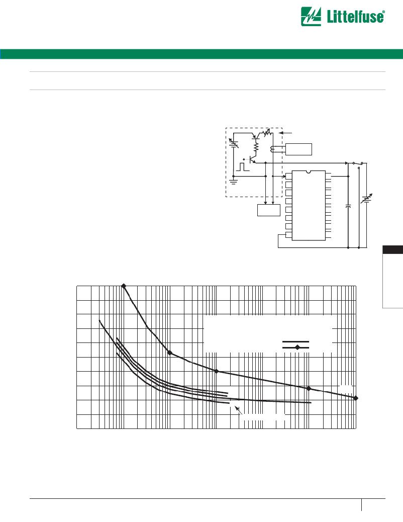
�Peak� Transient� Current� Capability� of� the� SP720�
�The� peak� transient� current� capability� rises� sharply� as� the� width� of� the�
�current� pulse� narrows.� Destructive� testing� was� done� to� fully� evaluate� the�
�SP720’s� ability� to� withstand� a� wide� range� of� transient� current� pulses.� The�
�circuit� used� to� generate� current� pulses� is� shown� in� Figure� 5.�
�The� overstress� curve� is� shown� in� Figure� 6� for� a� 15V� supply� condition.� The�
�dual� pins� are� capable� of� 10A� peak� current� for� a� 10μs� pulse� and� 4A� peak�
�current� for� a� 1ms� pulse.� The� complete� for� single� pulse� peak� current� vs.�
�pulse� width� time� ranging� up� to� 1� second� are� shown� in� Figure� 6.�
�VARIABLETIME� DURATION�
�The� test� circuit� of� Figure� 5� is� shown� with� a� positive� pulse� input.� For� a�
�+�
�R� 1�
�CURRENT� PULSE� GENERATOR�
�negative� pulse� input,� the� (-)� current� pulse� input� goes� to� an� SP720� ‘IN’�
�input� pin� and� the� (+)� current� pulse� input� goes� to� the� SP720� V-� pin.� The�
�V+� to� V-� supply� of� the� SP720� must� be� allowed� to� float.� (i.e.,� It� is� not� tied�
�-�
�V� G�
�CURRENT�
�SENSE�
�(-)�
�to� the� ground� reference� of� the� current� pulse� generator.)� Figure� 6� shows�
�the� point� of� overstress� as� defined� by� increased� leakage� in� excess� of� the�
�data� sheet� published� limits.�
�(+)�
�1� IN�
�V+� 16�
�The� maximum� peak� input� current� capability� is� dependent� on� the� V+� to� V-�
�voltage� supply� level,� improving� as� the� supply� voltage� is� reduced.� Values�
�2� IN�
�3� IN�
�IN� 15�
�IN� 14�
�+�
�of� 0,� 5,� 15� and� 30� voltages� are� shown.� The� safe� operating� range� of� the�
�transient� peak� current� should� be� limited� to� no� more� than� 75%� of� the�
�measured� overstress� level� for� any� given� pulse� width� as� shown� in� Figure� 6.�
�VOLTAGE�
�PROBE�
�4� IN�
�5� IN�
�6� IN�
�SP720�
�IN� 13�
�IN� 12�
�IN� 11�
�C1�
�-�
�When� adjacent� input� pins� are� paralleled,� the� sustained� peak� current�
�7� IN�
�IN� 10�
�capability� is� increased� to� nearly� twice� that� of� a� single� pin.� For� compari-�
�son,� tests� were� run� using� dual� pin� combinations� 1+2,� 3+4,� 5+6,� 7+9,�
�10+11,� 12+13� and� 14+15.�
�R� 1� ~� 10� ?� TYPICAL�
�V� G� ADJ.� 10V/A� TYPICAL�
�C1� ~� 100� μ� F�
�8� V-�
�IN� 9�
�5�
�FIGURE� 5.� TYPICAL� SP720� PEAK� CURRENT� TEST� CIRCUIT�
�WITH� A� VARIABLE� PULSE� WIDTH� INPUT�
�10�
�9�
�8�
�CAUTION:� SAFE� OPERATING� CONDITIONS� LIMIT�
�7�
�6�
�5�
�4�
�THE� MAXIMUM� PEAK� CURRENT� FOR� A� GIVEN�
�PULSE� WIDTH� TO� BE� NO� GREATER� THAN� 75%�
�OF� THE� VALUES� SHOWN� ON� EACH� CURVE.�
�SINGLE� PIN� STRESS� CURVES�
�DUAL� PIN� STRESS� CURVE�
�3�
�2�
�1�
�0�
�0V�
�5V�
�30V�
�V+� TO� V-� SUPPLY�
�15V�
�15V�
�0.001�
�0.01�
�0.1�
�1�
�10�
�100�
�1000�
�PULSE� WIDTH� TIME� (ms)�
�FIGURE� 6.� SP720� TYPICAL� SINGLE� PULSE� PEAK� CURRENT� CURVES� SHOWING� THE� MEASURED� POINT� OF� OVER-STRESS� IN�
�AMPERES� vs� PULSE� TIME� IN� MILLISECONDS� (T� A� =� 25� o� C)�
�w� w� w.� l� i� t� t� e� l� f� u� s� e� .� c� o� m�
�231�
�发布紧急采购,3分钟左右您将得到回复。
相关PDF资料
SP721ABG
TVS ARRAY ESD 6 INPUT 8-SOIC
SP721ABT
TVS ARRAY ESD 6 INPUT 8-SOIC
SP723ABT
TVS ARRAY ESD 6 INPUT 8-SOIC
SP723APP
TVS ARRAY ESD 6 INPUT 8-DIP
SP724AHTG
TVS ARRAY ESD 4 INPUT SOT-23
SP724AHT
TVS ARRAY ESD 4 INPUT SOT-23
SPC02SVDN-RC
CONN JUMPER SHORTING .100" GOLD
SPC02SVGN-RC
CONN JUMPER SHORTING .100" GOLD
相关代理商/技术参数
SP720ABTG
功能描述:TVS二极管阵列 30V 1A 3pF 14 Input RoHS:否 制造商:Littelfuse 极性: 通道:4 Channels 击穿电压: 钳位电压:11.5 V 工作电压:2.5 V 峰值浪涌电流:20 A 安装风格:SMD/SMT 端接类型:SMD/SMT 系列: 最小工作温度:- 40 C 最大工作温度:+ 85 C
SP720ABTG
制造商:Littelfuse 功能描述:Diode 制造商:Littelfuse 功能描述:DIODE, TVS, 3pF, SOIC-16
SP720ABTG-CUT TAPE
制造商:LITTELFUSE 功能描述:SP720 Series 3 pF Surface Mount Electronic Protection Array for ESD - SOIC-16
SP720AP
功能描述:TVS二极管阵列 SP720AP RoHS:否 制造商:Littelfuse 极性: 通道:4 Channels 击穿电压: 钳位电压:11.5 V 工作电压:2.5 V 峰值浪涌电流:20 A 安装风格:SMD/SMT 端接类型:SMD/SMT 系列: 最小工作温度:- 40 C 最大工作温度:+ 85 C
SP720APP
功能描述:TVS二极管阵列 14 CH DIODE ARRAY RoHS:否 制造商:Littelfuse 极性: 通道:4 Channels 击穿电压: 钳位电压:11.5 V 工作电压:2.5 V 峰值浪涌电流:20 A 安装风格:SMD/SMT 端接类型:SMD/SMT 系列: 最小工作温度:- 40 C 最大工作温度:+ 85 C
SP720APP - LITTELFUSE
制造商:Littelfuse 功能描述:DIODE TVS 制造商:Littelfuse 功能描述:DIODE, TVS
SP720APP
制造商:Littelfuse 功能描述:TVS DIODE ARRAY
SP720APP
制造商:Littelfuse 功能描述:THYRISTOR ARRAY TVS